A simple, “layman term” guide to assist you in choosing the perfect air compressor size, type, pipe, and accessories.
When it comes to choosing the right compressor size and type, there are several factors to consider. First and foremost, understanding your air demand is essential. This refers to the amount of compressed air your facility and its production systems and processes require to power cylinders, valves, tools, or equipment. By calculating the total cfm (cubic feet per minute) requirement of your pneumatic items, and applications you can determine the ideal compressor size to meet your needs.
Let’s start with a simple question.
“When was the last time you performed a study of your compressed air system, including your generating equipment, air quality, dewpoint, cooling system, storage, flow, pressure, and the distribution pipework to confirm their suitability and energy consumption?”
In our experience, many compressed air users rarely, and sometimes never perform an analysis of their station and its distribution network. Having studied over 1,000 compressed air systems, we can confidently confirm that an air demand analysis study can reduce the costs, (both hydro and maintenance), of compressing air and deliver significant benefits to your operation. Furthermore, we have access to Ontario Government funding for almost any compressed air improvement project >$500.00 that you may be considering.
Because circumstances in manufacturing and production facilities often change due to new equipment, expansions, compressed air leaks, and increased production, a compressed air study makes perfect sense.
A typical study will last between 7 to 9 days, ensuring that the data collected reflects two weekends and Monday to Fridays production. If the system operators are able to leave the compressed air system fully functional over the weekends, despite production levels, the study will almost certainly highlight unnecessary superficial demands, and the approximate loss of compressed air due to pipe work, hose, and fitting leaks.
Upon completion of an air demand analysis study a benchmark will have been established, from which we can enhance, retrofit, upgrade, or completely replace the air compressor station, its’ piping network, air dryers, filtration, air receiver storage tanks, air tools, uses, and nozzles.
Most importantly, you will have lifted the lid to see 1st hand; the efficiency of your system based on factual date and time-stamped data.
After all, we can’t improve what we don’t measure.
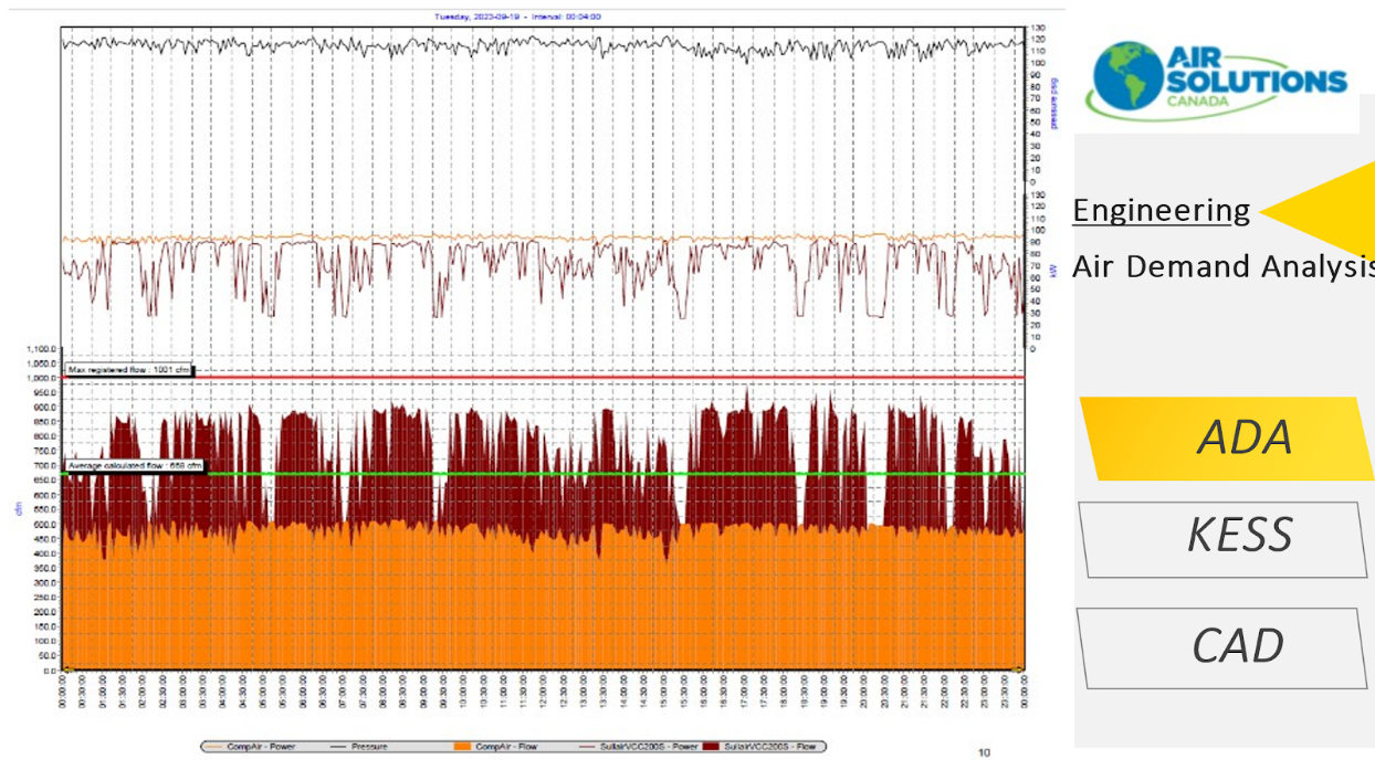
The analysis data logging setup looks like this. Multiple compressors can be monitored simultaneously.

The date and time stamped overview pages (9 days) indicate the cfm flow, the kW consumption and psig

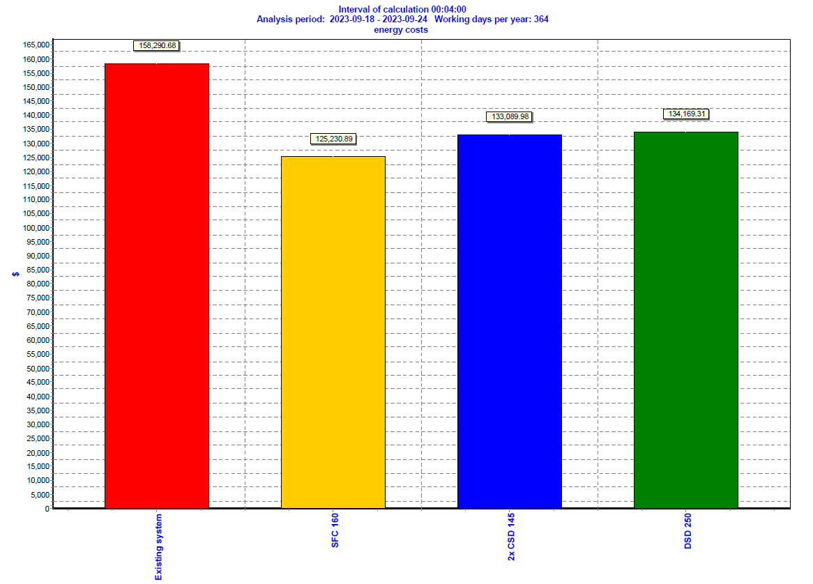
The following bar graph example, (1 of 3), shows the comparisons between the existing system, which was analyzed, and they provide options for improved configurations. Save on Energy incentives will be available for you once you have this type of base case benchmark data. Don’t be surprised if up to 50% of your project costs can be covered under the Save on Energy Incentive.
The graphs confirm:
- kW comparisons, and these will qualify for an incentive of $1,200 per kW reduced.

- kW/hr. comparison, and these will qualify for $0.13c per kW/hr. reductions.

- The final bar graph confirms the $ energy saved per annum. This is the gift that keeps on giving.

Another crucial consideration is the type of air compressor. Two of the most common types found in a standard manufacturing, service, or production facility are reciprocating piston compressors and rotary screw compressors. Reciprocating compressors use pistons to compress air, making them suitable for lighter applications such as DIY projects or small workshops. Reciprocating compressors struggle to produce compressed air on a continuous basis, because of their limitations in duty cycle times. If they aren’t sized correctly, piston compressors may not be capable of supplying the required volume, (CFM), of compressed air to the end users. The pump is designed to run 50% of the time and then rest, in order cool itself, for the remaining time. Piston compressors offer the following advantages; lower capital costs, Simplistic maintenance, High pressure capabilities. They also come with some disadvantages, such as high noise levels, short life expectancy, they consume large areas of real estate, expel excessive heat, and pass oil and water contamination. On the other hand, rotary screw compressors are designed for heavy-duty industrial tasks, and provide continuous, high-volume airflow, 24/7, if required. Screw compressors are compact, quiet, have a 100% duty cycle capability, extensive warranty coverage and deliver better air quality. Some disadvantages are also apparent, such as capital costs, and skilled labour maintenance rebuild requirements.
A recent survey confirmed that 80% of 340 end users who where asked “do you prefer piston or rotary screw compressors” answered rotary screw because of performance, reliability, size, quality, and noise levels. The 20% of piston compressor fans, based their opinion on lower capital cost, and ease of maintenance service.
When selecting a compressor, it's also important to assess your available power source. Electric air compressors are the most common type in a factory setting and require a reliable source of electricity. Electrically driven compressors are generally quieter and more suitable for indoor use. However, if you need a compressor for outdoor, or remote locations, a portable compressor with a gasoline, or diesel engine might be a better choice. Many electric drive air compressor users, install an emergency rental hook up valve arrangement. This provides simple and easy connection of a temporary, tow along style Mobil Air compressor – should the electric drive equipment fail.


Compressor room heat and ventilation
The location of your air compressor station is an important consideration. It will need to be easily accessible for equipment placement, and future removal of heavy items, such as motors, air ends, and potentially entire pieces of equipment. As a minimum, we recommend installing double doors, and in a perfect world large roll up door access openings. Accessibility for service and maintenance technicians is also important, avoiding narrow corridors and staircases if at all possible.
The room should be very well ventilated, when using air cooled compressors and dryers. Air compressor overheating is the number one reason for compressor failure. Installing low level, fresh air intake louvers is a best practice. The position of the louvre fins can be controlled with a manual lever, or automatically controlled using a damper actuator, such as Belimo.
Positioning the fresh air intake louvers at the lowest level possible is advisable. If the louvre is subject to snow falls, the lowest part of the horizontal frame should be set above the expected snow line. Including a provision to add filter frames or filter media will help to keep the compressor room clean, extend the service life of the air intake filters, and keep the air and oil coolers clean. Clean coolers will help to prevent air compressor over temperature.
During the compressor room design phase, bear in mind that the compressors will create large amounts of heat. This creates a challenge, and also a fantastic energy recovery opportunity. >75% of the heat generated by an industrial rotary screw compressor can be captured and repurposed.
Hot air discharge duct work is strongly recommended, as this will channel unwanted heat of compression out of the room to an external wall, or roof opening during the summer months. Avoid discharging hot air exhaust onto other compressed air equipment. Ensure that the hot air discharge cannot be re-ingested through the fresh air intake louvers, by spacing them far enough apart in strategic potions, when designing your room. Removing the heat from the compressor room provides several benefits. These include better operating and running temperatures, reduced loading on downstream filtration and air dryers, while extending the service life expectancy of the equipment inside the compressor room.

In addition to the benefits that correctly cooling a compressor room will provide, there is also a fantastic opportunity to space heat areas too. By making a small modification to the hot air exhaust duct, and adding a simple damper mechanism, and a louvered outlet, massive amounts of space heating can be captured for use during the colder months. The damper can be controlled automatically from a thermostat if you choose to recirculate the heat inside the compressor room. Many end users extend this space heating duct outlet into a warehouse, or an area where normally wasted heat would be beneficial. There are some limitations as to the distance that the hot air can travel before the temperature drops, so consulting a professional is advisable. In addition, reclaiming the heat of compression often means that gas heaters can be dialed back. Gas providers, such as Enbridge Gas will typically incentivize the installation of the heat recovery ducts, based on the calculated gas consumption reduction.
Heat recovery for water heating
Air cooled and water cooled rotary screw compressors also provide an excellent opportunity to capture heat for the heating of process fluids, food and beverage kettles, boiler feedwater, and even water for showers and washrooms. Fluid to fluid heat exchangers will provide you with an “on demand” process and heating water temperatures up to 195°F.
Water cooled compressors provide the most simplistic “plug and play” configuration for continuous process heating applications, providing year round energy savings by connecting the discharged hot cooling water directly to a process.
Air cooled compressors can be ordered with, or retrofitted, with an additional oil to cold process water heat exchanger. This additional cooler provides a number of advantages. The hot compressor oil exchanges with external cooling water to a) reduce the oil and operating temperature of the air compressor, and b) generate hot water for use in external process applications.
It is possible to ‘harvest’ approximately >17,000 BTUs of heating energy per hour for every 35 CFM of compressed air generated. In many cases heat recovery efficiencies of up to 90% are frequently attained.
Over and above the easy to achieve energy savings, the environmental benefits of heat recovery can also impact the reduction of your carbon footprint.


Air receiver storage tanks
Do you need compressed air storage? Not necessarily.
Do we recommend Storage? Absolutely, 110%.
Why? Great question.
Air receiver storage tanks provide several important features, advantages, and benefits within a compressed air structure; however, tanks are often overlooked during the design stage of a system.
Tanks are referred to in various designations. As Louis Armstrong sang, “you like potato, I like potatoe”.
Tanks, Vessels, Storage Tanks, Reservoirs, Storage Vessels, Storage Tanks, are all one and the same.
In essence, you can never have enough, or too much storage. As a basic “rule of thumb”, you will have a minimum of 3 gallons of storage to 1 cfm of compressed air, however manufacturers, such as Kaeser recommend a 5 to 1 ratio.
Save on Energy “prescriptive” incentive rebates are simple to apply for and will provide the following financial return for your air receiver upgrade project. If you would like assistance in the application and execution process, Air Solutions Canada provides this resource at no charge, as a value added service.

As for the features, advantages, and benefits there are several.
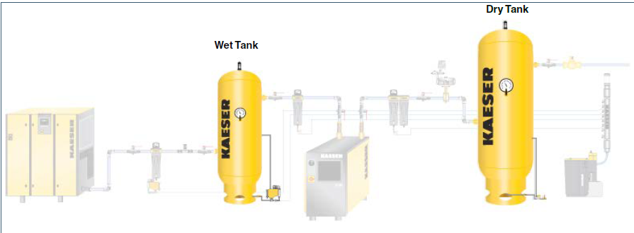
Tanks create cyclonic motion, by virtue of their shape. Compressed air will enter the tank at the bottom and exit from the top. This will expand the air, slow the velocity, and provide a slight temperature reduction. The cyclonic motion, (salad spinner style), encourages moisture to be transported to the internal surface of the tank, and gravity drives condensate to the base of the tank. The automatic condensate drain trap ecodrain removes this unwanted contamination.
Be sure to send the oil/water condensate to an oil/water condensate management separator prior to it entering a floor drain.
Removing moisture at this point in the system, upstream of the air dryer, is referred to as “a wet tank”. This removal of liquids will in turn reduce the moisture and oil loading on the dryers and filters. A “dry tank” will reside downstream of the air dryer. Storing clean dry compressed air will help to stabilize system pressure, feed demand surges, and increase the time that the air compressor runs unloaded. Running the compressor in an unloaded state will reduce energy consumption, creating hydro savings., and potentially increasing energy incentive rebate values.

Master controls
If your system includes multiple air compressors, a master controller will ensure that the compressed air equipment performs optimally.
A master controller, (Kaesers Sigma Air Manager, SAM 4.0), will:
Save energy by:
- Reducing the run time of compressors
- Running the compressors at a lower pressure
- Reducing the air lost to leaks
- Lowering the artificial demand
Reduce maintenance costs by:
- Extending valve service life expectancy – with fewer cycles and switching
- Reducing motor stops and starts – resulting in longer motor service life
- Balancing run times – reducing PM service frequency
Maximize operational efficiency by:
- Improved production equipment performance and reliability
- Sequencing the compressors to ensure equal running hours, based on the plant demand.
- Reduce downtime due to low pressure alarms
- Decrease product scrap and quality issues
- Creating algorithms to streamline efficiency and operation of the compressed air equipment
 What size of air compressor do I need?
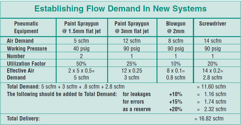
When selecting which size and type of air compressor you require, the first thing we need to establish is how much compressed air flow and pressure is needed to power your tools, valves, cylinders, spray guns, breathing apparatus, nozzles, air knives, and end users. Pneumatic driven equipment manufacturers will publish technical specifications for their products in regard to cfm volume, and psig pressure. Bear in mind that these types of equipment won’t all “fire” at exactly the same time.
Here are 5 steps to assist you with your sizing and selection, otherwise, please contact us for assistance.
Step 1: To determine the air consumption of each tool:
- Check the manufacturer's user manual, or specifications for each tool, nozzle, cylinder, or valve to confirm the air consumption rating. It is usually given in CFM or SCFM (Standard Cubic Feet per Minute).
- If the rating is given in SCFM, convert it to CFM by multiplying it with the appropriate correction factor based on the atmospheric conditions (temperature, humidity, and altitude) in your specific environment.
Step 2: Add up and total the CFM air consumption of all of the pneumatic items you plan to use simultaneously. This will give you the total CFM requirement.
Step 3: Consider the pressure drop:
- Determine the pressure drop that occurs in your compressed air distribution system, including filters, dryers, hoses, and fittings.
- Multiply the pressure drop per 100 feet of the actual length of your compressed air distribution piping system to calculate the total pressure drop in psi.
Step 4: Determine the generating pressure required at the air compressor:
- Add the desired operating pressure of the tools and other items to the pressure drop you calculated in the previous step. This will give you the required pressure that the air compressor should be set at. Be sure not to overlook the importance of considering the discharge pressure required for your specific applications. Different tools and equipment have varying pressure requirements, and it's crucial to choose a compressor that can deliver the necessary pressure consistently. Be sure to consult the manufacturer's specifications for your tools and match them with the appropriate compressor.
Step 5: Calculate the required CFM:
- Consider the duty cycle, (the percentage of time they will be in use), of your tools and other items. Multiply the total CFM requirement from step 2 by the duty cycle to get the required CFM for your compressor. As a rule of thumb, an oil injected industrial rotary screw compressor produces 4.5 CFM per hp. Example, to generate 225 CFM @ 100psig, you will need a 50hp machine.
- It's important to note that these calculations provide an estimate only. It's recommended that you consult with a compressed air and energy solution provider to ensure accurate sizing of equipment, accessories, and piping for your specific application.

Conclusion
While selecting the right compressor size and type, it's important to consider the long-term cost implications. Energy efficiency plays a significant role in determining the overall operational costs of a compressor. Look for compressors with energy-efficient features, such as high efficiency motors, and most importantly their specific power required to produce 100cfm/kW. Compressed Air and Gas Institute is a 3rd party validation organization, which compares all major manufacturers' machines against one another, and publishes the results via their website.
In conclusion, choosing the right compressor size and type is a decision that should be made after careful consideration of your specific air demand, power source, tank size, discharge pressure requirements, and long-term cost implications. By taking the time to assess these factors, you can ensure that you select a compressor that meets your needs effectively and efficiently. Remember, 70% of the costs that you’ll incur over the next 10 years of air compressor ownership will be energy! Only 15% will be maintenance and 15% is capital costs. So, prioritize your needs, consult manufacturer guidelines, and make an informed decision that is right for you. Consult with a compressed air and energy specialist.

